Ehsan Roshani

My Projects

Brilliance H330 – FEM Reverse Engineering

Project Code: PRJ-BRH330-FEM-RE

Objective

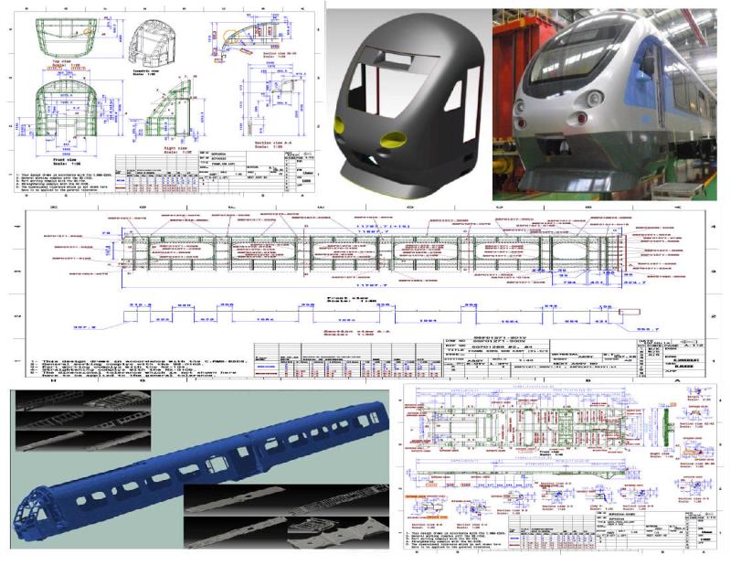
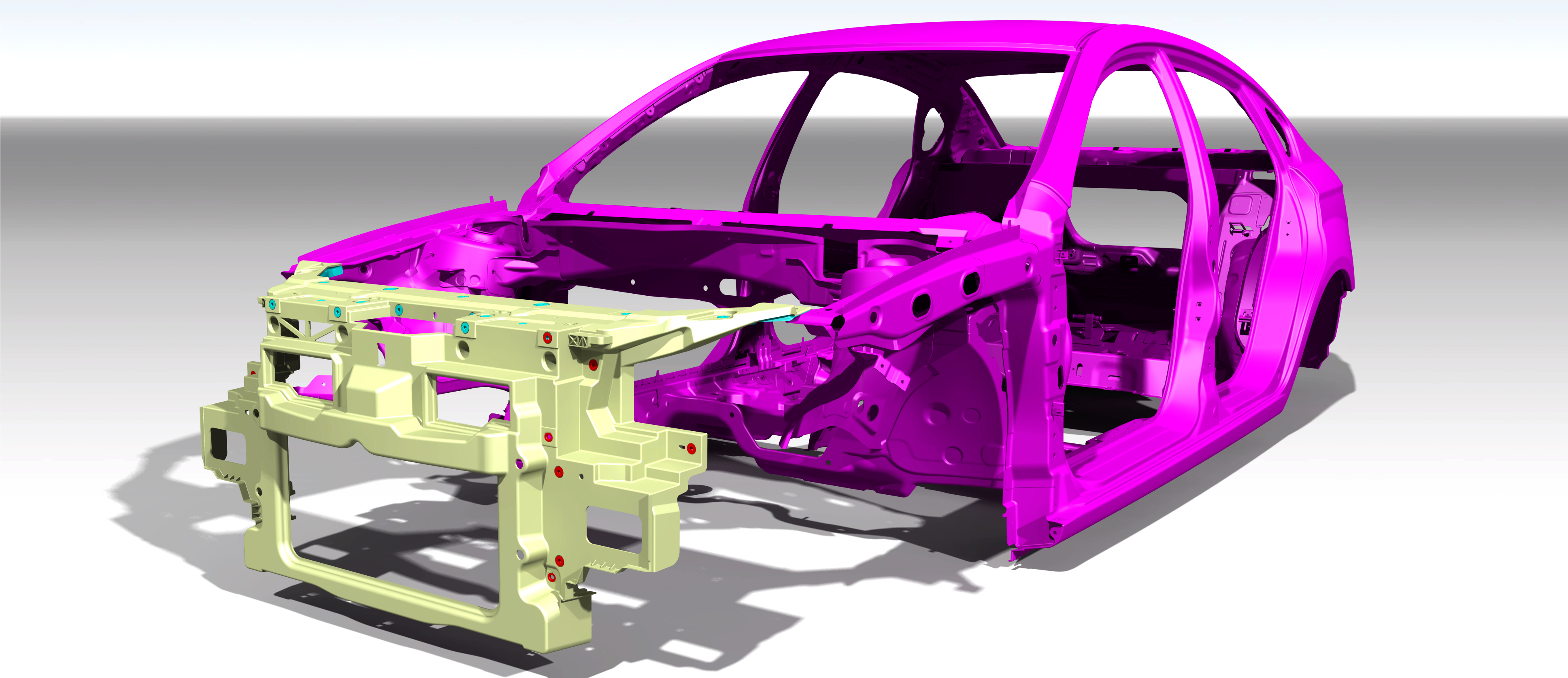
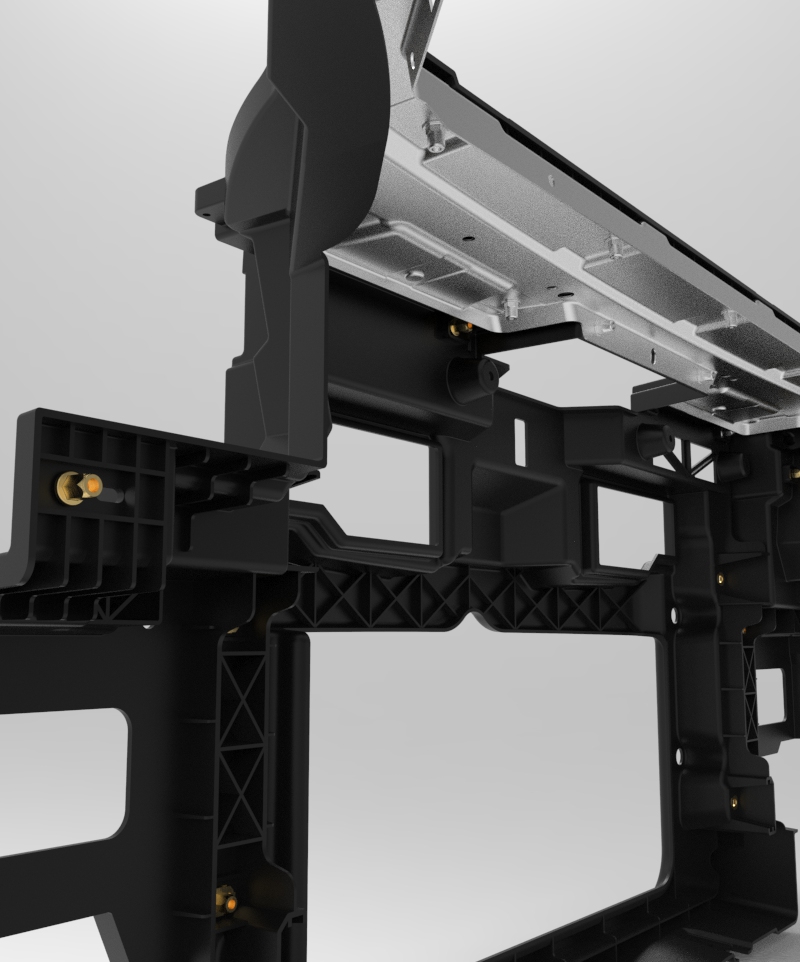
The project aimed to reverse engineer and localize the Front End Module (FEM) of the Chinese Brilliance H330 vehicle, originally imported by SAIPA in CKD format. The main goal was to enable full local production after the original Chinese supplier ceased part deliveries, while ensuring precise dimensional compatibility with SAIPA’s robotic and manual assembly lines.

Problem Statement

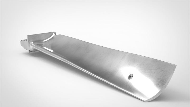
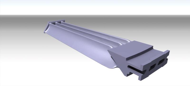
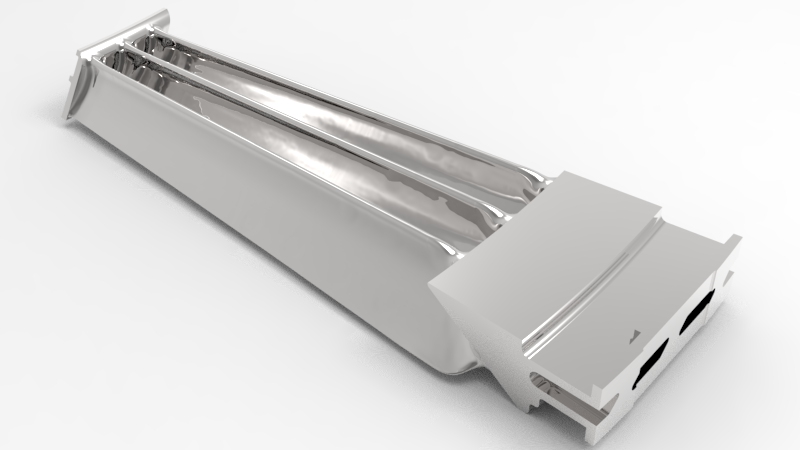
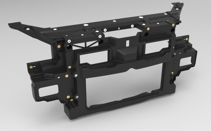
After partial localization, the unavailability of OEM parts posed a significant risk to production continuity. The critical challenge was to replicate a large plastic component—approximately 1300 mm in width—with minimal deviation to allow seamless assembly without any change to robots, fixtures, or adjacent components.

My Role

  • Project Manager responsible for full 8-month execution
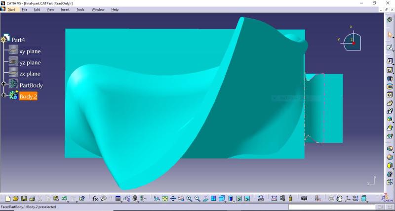
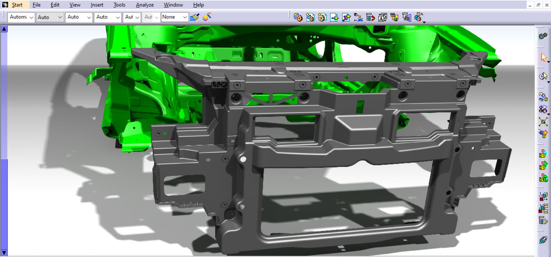
  • Performed CAD modeling and revision in CATIA V5
  • Led coordination with SAIPA QC, CMM lab, metallurgy team, fixture designers, and documentation staff

Technical Details

  • Software: CATIA V5, CMM tools
  • Techniques: 3D point cloud alignment, surfacing, rapid prototyping, mold coordination, fixture design
  • Material: Glass fiber-reinforced polypropylene (PP+GF6)

Process

Started with CMM scanning and point cloud processing, followed by surfacing in CATIA and prototype validation. Revisions were based on deviation reports, and the final mold was produced in China. Fixture design and material testing were conducted in parallel to ensure manufacturability and precision.

Challenges and Solutions

  • Lack of datasheets: resolved with CMM-based measurement
  • Post-mold deformation: solved with reverse offset modeling
  • International supplier coordination: handled via structured technical communication

Results

  • Dimensional deviation below 0.3 mm
  • Cost reduced from $120 to $80 per part
  • Component currently in serial use in SAIPA’s production line

Gas Recovery – Marun 6 Field

Project Code: PRJ-MRN6-FLR-RCV

Objective

Design and development of a modular flare gas recovery station for the Marun 6 oil field in southern Iran. The system was engineered to collect low-pressure flare gas, remove contaminants and moisture, and compress it in two stages for reinjection into the production network — reducing environmental impact and recovering valuable hydrocarbon resources.

Problem Statement

Excessive flaring at Marun 6 caused significant resource loss and environmental damage. The project required a compact, explosion-proof mechanical system capable of processing contaminated flare gas starting at 0.5 bar and compressing it to 40 bar via staged compression — all within the constraints of two containerized skids, designed for transportability and on-site space limitations.

My Role

  • Served as Mechanical Designer at Tamkar Gas Equipment Co.
  • Modeled the entire system using CATIA V5, based on concept inputs from senior engineers
  • Responsibilities included full 3D layout and modeling of the two-stage compression system:
    • Stage 1: Oil-injected screw compressor (0.5 → 16 bar)
    • Stage 2: Reciprocating compressor (16 → 40 bar)
  • Detailed design of gas-liquid separators, filters, dryers, demisters, and oil coolers
  • Modeled modular skid structures (two 18-ft containers) and complete piping/tubing networks
  • Selected and positioned OEM components (e.g., Parker, Swagelok) including:
    • Swivel joints, check valves, relief valves, safety valves, and instrumentation valves
    • Schedule 40 carbon steel pipes, flanges, and fittings
  • Collaborated with QA and instrumentation teams to enhance understanding of field constraints, ATEX zones, and pressure regulation

Technical Details

  • Software Used: CATIA V5
  • Design Standards Applied:
    • ASME B31.3 – Process Piping
    • ASME B16.5 – Flanges and Fittings
    • ASME B36.10M – Steel Pipes (Schedule 40)
    • ISA Standards – Instrumentation and Tubing
    • ATEX Directive 2014/34/EU – Hazardous Area Design
    • ASME Section IX – Welding Qualifications

Process Overview

  • Transformed conceptual layouts into production-ready 3D assemblies
  • Designed components to fit within modular skids for compact installation
  • Generated detailed 2D drawings and BOMs for procurement and fabrication
  • Ensured compliance with pressure integrity, service accessibility, and ATEX requirements

Challenges and Solutions

  • Low inlet pressure (0.5 bar): Solved via two-stage compression with intermediate buffering
  • Explosion-proof requirements: Met through ATEX-compliant component selection and zone classification
  • Limited installation space: Addressed with vertically stacked, container-based skid design
  • Lack of local precedents: Overcome through international standard review and OEM technical literature

Results

  • Delivered complete mechanical design package with 3D models, fabrication drawings, and specifications
  • Project implemented with ~$1M investment funded by Iran’s Innovation and Prosperity Fund
  • Recognized as a national benchmark in flare gas recovery and emissions control
  • Advanced domestic capabilities in high-pressure gas system design and sustainable energy solutions

BBC-D13 Gas Turbine Blade Engineering

Client: Tajrobeh Noor Co.

Role: Lead Design Engineer

Duration: ~8 months

Software: CATIA V5

Project Overview

Reverse engineering and reindustrialization of blades No. 4 & 5 of the BBC-D13 gas turbine. The goal was to enable domestic manufacturing of spare blades under international sanctions, using only worn physical samples as input data.

Responsibilities

  • Led the modeling and design team in the reconstruction of blade geometry using manual cross-sectioning and point cloud analysis
  • Developed surface models with precise tangent continuity (G1/G2) using low-degree conic functions instead of high-degree splines to ensure manufacturing feasibility
  • Designed the complete tooling package:
    • Pre-form and final forge molds (multi-stage forging)
    • Machining fixtures and gauges for all production phases
    • Functional control jigs for dimensional inspection (CMM verified)
  • Delivered 2D manufacturing drawings with tolerances and machining allowances

Technical Challenges & Solutions

  • No CAD reference or drawings: Surface creation relied on conic-based curve fitting from imperfect point clouds to minimize deviation without introducing ripple artifacts
  • Reverse Engineering Strategy: Reconstructed each blade section using four curves (2 quadratic + 2 cubic), ensuring tangent continuity and curvature smoothness
  • Tooling Accuracy: Forging dies designed with consideration for material flow, shrinkage, and grain direction

Results

  • Functional prototypes successfully produced and validated via CMM
  • Enabled local forging and machining of turbine blades
  • Paved the way for domestic production of critical aero components in the absence of OEM support

Standards & Methodologies

  • ASME Y14.5 – GD&T for dimensioning
  • ISO 13715 – Undefined edge control
  • Forging simulation and drafting aligned with OEM-grade practice
  • Industrial experience in use of CATIA V5 GSD (Generative Shape Design) and RE modules for aerodynamic surface modeling

Automation Machinery Design & Execution

Company: ES-AL MAKİNA OTOMASYON Co.

Location: Istanbul, Turkey

Position: Mechanical Design Engineer

Duration: Jan 2020 – Mar 2022

Project Description:
As a mechanical design engineer at ES-AL Makina, I was fully responsible for the complete cycle of automation machine development – from concept and 3D design to fabrication, assembly, testing, and revision. The machines were mostly customer-specific and designed for the food and packaging industries, requiring rapid adaptability in both mechanical configuration and functional parameters such as speed, volume, and viscosity.

I managed all phases independently, including mechanism design, part detailing, component selection, BOM creation, and coordination with the manufacturing team. Fast revision cycles and parallel customer requests provided me with valuable experience in high-paced, custom engineering environments.

Examples of Machines Designed:

  • Tube filling machines for viscous and semi-viscous materials
  • Stick pack filling systems
  • Liquid filling machines for different container types
  • Single and double-walled tanks with electric heating elements
  • Automatic labeling machines and cap tighteners
  • Custom conveyor systems for integrated packaging lines

Key Responsibilities & Tools:

  • 3D design and assembly in SolidWorks
  • 2D drawings and production documentation
  • Selection of industrial components (motors, sensors, actuators)
  • Supervision of part fabrication, assembly, and testing
  • Rapid revision handling based on real-time customer feedback
  • BOM creation and support for serial production

Key Takeaway:
This period gave me hands-on experience with end-to-end engineering execution. It sharpened my ability to handle high-variation, fast-delivery projects with confidence and efficiency.

Edge Mill Machine – Reverse Engineering & Spiral Line Mill Design

Project Code: PRJ-EMM-SPRL-RE

Objective

Reverse engineering and technical redocumentation of a precision edge mill machine used for longitudinal edge beveling in spiral pipe production lines. The goal was to replicate and document the full machine structure for domestic manufacturing in absence of original design files.

Problem Statement

The machine—originally sourced from abroad—was installed at Safa Rolling Complex (FREYMAN – Mashhad, Iran) without any accompanying technical documentation. The client required complete disassembly, modeling, and drawing of the entire machine based solely on physical inspection and manual measurements under real-world shop-floor conditions.

My Role

  • Project Lead for disassembly, modeling, and documentation
  • Manual measurement and inspection of all components
  • Complete 3D modeling in CATIA V5
  • Creation of fabrication and assembly drawings with tolerances
  • Supervised junior team members and validated subcomponents
  • Delivered full technical package including:
    • ~800 modeled parts
    • Assembly layouts, exploded views, and shop-ready manufacturing drawings

Note: Although not involved in fabrication, hands-on work with real machinery gave me deep insights into tolerancing and manufacturability that no screen-only design experience could offer.

Machine Specifications

  • Application: Longitudinal edge beveling of steel plates for spiral pipe welding
  • Maximum plate width: 2500 mm
  • Machine dimensions: ~1000 × 1000 × 1000 mm
  • Number of parts modeled: ~800
  • Subsystems included:
    • Base frame and chassis
    • Gearboxes and roller units
    • Forming and guiding frames
    • Mechanical supports and alignment systems

Technical Details

  • Software Used: CATIA V5
  • Project Duration: ~3 months
  • Design Standards Applied:
    • ISO 2768-mK – General tolerancing
    • ISO 1101 – GD&T
    • ASME Section IX / ISO 13920 – Welding standards
  • Measurement Tools: Calipers, micrometers, dial gauges (manual)

Process Overview

  • Disassembled and manually measured each machine component on-site
  • Logged all dimensions into categorized spreadsheets
  • Reconstructed full 3D assemblies in CATIA
  • Generated 2D manufacturing and assembly drawings with full BOM
  • Verified consistency through digital mockup and cross-checked fit points

Challenges and Insights

  • No reference documents: Tolerances inferred using functional logic and engineering judgment
  • Manual-only measurement: Increased complexity but enhanced dimensional reasoning
  • Young team and no simulation tools: Required real-time decision-making and high attention to detail

Results

  • Complete technical documentation delivered to client
  • Enabled domestic production and future maintenance of strategic equipment
  • Workflow structure reused in similar reverse engineering projects
  • Strengthened my ability to lead multi-phase design with minimal initial data

VARGEL Linear Drive System

Project Code: VARGEL-LM-MOD

Duration: ~3 months

Role: Project Lead (Mechanical Design Manager, Toksel R&D Department)

Software: Autodesk Inventor

Project Overview

Development and reengineering of a modular linear motion system (VARGEL) intended to replace traditional screw-based actuators. The goal was to reduce production costs, improve reliability, and enable high-speed backlash-free operation without using threaded shafts.

Technical Description

VARGEL operates as a non-positive drive mechanism: it converts the rotation of a plain round shaft into axial motion using a precision roller-based mechanism. The system eliminates the need for lead screws or ball screws, achieving high-efficiency linear movement through mechanical rolling contact.

Key Contributions

  • Redesigned the original cast iron housing into custom aluminum extrusions for weight reduction and simplified machining.
  • Developed internal components with enhanced durability and optimized geometry based on manufacturability constraints.
  • Led a small cross-functional team through prototyping, fit-testing, and redesign cycles, adapting tolerances to in-house CNC capabilities.
  • Personally supervised mechanical testing of prototypes and verified design changes post-assembly.

Outcomes

  • Weight reduced by nearly 70% for certain sizes.
  • Production cost significantly lowered due to use of standard aluminum profiles.
  • Performance and stability improved by eliminating backlash and reducing friction losses.
  • Full documentation package prepared including BOMs, 2D/3D drawings, tolerance analysis, and assembly guidelines.

Reference Design Principles

  • Backlash-free motion
  • Release lever for manual reset
  • Overload protection via slip
  • Dust and humidity sealing for industrial environments
  • Modular design for custom pitch and direction control

Note: Due to the proprietary nature of the internal mechanism, detailed geometry is not disclosed. However, the development was heavily inspired by modern threadless linear actuation principles and adapted for Toksel’s unique machine architecture.

Digitizing Hyundai Rotem Railbus Structures

Project Code: SAP00338

Client: IRICO – Iran Khodro Rail Industries Co.

Origin of Design: Hyundai Rotem (South Korea)

Project Duration: 3 months – Team of 3 Engineers

Software Used: CATIA V5

Role: 3D Modeler, Drafting Specialist, and Local PDM Developer


Project Summary:
This project involved the complete 3D modeling and technical documentation of the structural body frames of A-CAR and B-CAR railbus wagons, based on original paper drawings obtained from Hyundai Rotem (South Korea). The project was commissioned by IRICO (Iran Khodro Rail Industries Co.), with the goal of digitizing all design data and creating a reliable technical archive for domestic manufacturing and localization.


Scope of Modeling:

  • Roof structure
  • Main floor frame
  • Side walls
  • Driver’s cab (CAB)


My Responsibilities:

  • 3D modeling of structural components
  • 2D drafting of assemblies and parts
  • Designing and implementing a local PDM workflow

Engineering Workflow Innovation:
Due to the absence of collaborative platforms such as 3DEXPERIENCE or ENOVIA, we created a local PDM system using native capabilities in CATIA V5.
Key elements included:

  • Assembly structure based on Publications, Context Management, and modular logic
  • Parallel teamwork on shared assemblies without conflict or data loss
  • A central Excel spreadsheet linked to all parts, drawings, and assemblies for parametric control

This experience gave me practical knowledge in deploying lightweight PDM systems and allowed me to take initiative as a process consultant for similar projects.


Technical Highlights:

  • Over 2,000 unique parts modeled
  • More than 8,000 total components including repetitions
  • Excel-driven CATIA modeling pipeline for automation and consistency
  • Fully linked technical archive including drawings, assemblies, and part libraries


Key Achievements:

  • Digitized Hyundai Rotem’s A-CAR and B-CAR railbus structures from legacy paper drawings
  • Delivered a production-ready technical archive
  • Implemented a scalable PDM-like system within CATIA V5 without external platforms
  • Significantly reduced modeling time with high accuracy and team coordination

Teaching Reverse Engineering & Surface Modeling with CATIA

Institution: Tehran Institute of Technology

Location: Tehran, Iran

Role: CATIA Instructor – Reverse Engineering & Surface Modeling

Duration: 2015 – 2020 (5+ years, 5000+ teaching hours)

Summary:
Alongside my industrial design career, I worked as a professional CATIA instructor for over 5 years, focusing primarily on reverse engineering and digitizing complex shapes using CATIA and Quick Surface. My teaching approach was highly practical, project-based, and centered on recreating precise 3D geometry from physical parts or scanned data.

Key Teaching Topics:

  • Quick Surface workflows and editing scanned geometry
  • CATIA GSD (Generative Shape Design) – curve networks, patch surfaces, tangency control
  • Digitizing shapes from physical parts, photos, or measurement data
  • Reverse engineering industrial components with surface accuracy and continuity
  • Preparing Class B/Class A surfaces for product design and manufacturing

Educational Approach:
I focused on real-world applications and hands-on challenges. Instead of teaching CATIA as a set of tools, I trained students to think like engineers. Many of my top students were later recruited into companies I worked with, helping me build fast, reliable, and synchronized design teams.

Training Locations:

  • Tehran Institute of Technology – Sa’adat Abad Branch (4000+ hours)
  • Narmak and Piroozi Branches (500+ hours each)
  • Semnan – Corporate training for Parmida Rubber and Azad University